Servos are a class of actuator that have built-in positioning feedback. They are composed of a motor and a circuit with a potentiometer (variable resister) and time decoders that are used for feedback and positioning. They are controlled with time-based commands known as pulse-width-control. Pulse-width-control is a cousin of PWM (pulse width modulation).
For our purposes, we can think of servos as coming in two basic kinds: standard (180 degree) models, or continuous rotation (360 degree) models. Lots of variations within each type exist. Recently developed digital servos have microcontrollers built-in, simpler models (the ones we will be using) were developed for RC vehicles and are controlled by external electronics like an Arduino or a specifically designed circuit.
The electrical connections are the same for standard and continuous servos, but the logic of the code that underlies their control differs.
Making Connections
Basic Landmarks of an RC servo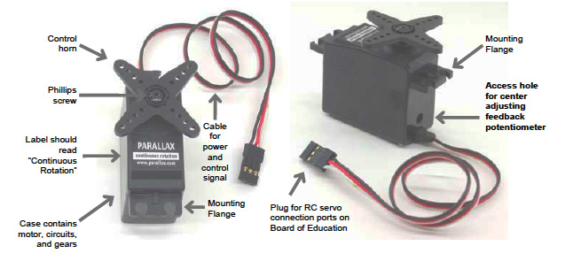
Servos have a permanent cable with three leads that passes through the housing. They are color coded:
- red –> connects to +V. 5V OUT on Arduino, or external battery (BETTER)
- black –> connects to GROUND (GND on Arduino AND external battery ground (when used)
- white –> connects to a DIGITAL pin on your Arduino (match this PIN in code, see below)
Voltage should NOT EXCEED 7.2V MAX. For most cases, 5-6V (4AA batteries) is sufficient. For unloaded (nothing attached to the control horn), initial tests single servos can be driven from the USB port. It is BEST to always have external power for the servo. In this case, connect the ground from the servo power to a GND pin on your Arduino.
Controlling A Standard Servo
Importing the Servo.h Library
The Arduino IDE ships with a built in servo library that greatly simplifies controlling these motors. The library must be imported into your sketch for use.
You can add a library through the Sketch menu:
Sketch --> Import Library... --> Servo.
Or, you can type this line at the top of your code:
#include <Servo.h>
Instantiate the Servo object — name your object:
Servo myservo;
In the setup() call of your sketch you need to attach the servo to a PIN. This is the digital pin that you chose and connected to the servo’s signal wire (white lead, above).
myservo.attach(servoPin);
Within the loop() call you can set the position of the servo by passing desired position values with the write(val) function. This function can be used in two ways. Either by passing positions in degrees (0-180) or by passing time values (uS, microseconds) that correspond to positions (550 – 2400).
The time signal range reflect the timing of most RC servos, and are hardware defined. A signal length of 1500uS will center the servo. A signal length of about 550uS will move the servo to one end of its range, and 2400uS moves the servo horn to the other end of its range.
myservo.write(90); // set the servo to 90 degree (centre)
myservo.write(1500); // set the servo to 90 degrees (centre) with 1500uS pulse
IMPORTANT: It will take a bit of time for the servo to move to the desired position. This should be accounted for before sending to the next position.
Sample Code
The following code sweeps the servo horn from one end of its range to the other and then back again. Two types of calls, degrees and time-based are used. The behaviour of the servo is the same with these two methods.
// DegreeTime_ThreePositions.pde
// Based upon original code by BARRAGAN
// modified by Steve Daniels (Nov, 2009)
// www.hex705.com
// www.spinningthweb.org

#include <servo.h>

Servo myservo;    // create servo object to control a servo
                           // a maximum of eight servo objects can be created

int pos = 0;         // variable to store the servo position
int servoPin=8;   // set the pin to which you have connected a servo

void setup()
{
myservo.attach(servoPin);  // attaches the servo on pin 9 to the servo object
pinMode(13,OUTPUT);
}

void loop()
{

digitalWrite(13,LOW);  // turn LED off

//  LED is OFF during degree based commands -- you should see no difference in servo behaviour
//  values between 0 and 180 are interpretted as degrees

myservo.write(0);
delay(2000);

myservo.write(90);
delay(2000);

myservo.write(180);
delay(2000);

digitalWrite(13,HIGH);  // turn LED on

//  LED is ON during time based commands -- you should see no difference in servo behaviour
//  values greater than 544 and less than 2400 are interpretted as microseconds

myservo.write(544);
delay(2000);

myservo.write(1500);
delay(2000);

myservo.write(2400);
delay(2000);

}